Unlocking Nature’s Pest Control: How to Attract Beneficial Spiders to Your Garden
Imagine a garden teeming with life, not just the vibrant blooms and verdant foliage you meticulously cultivate, but also a thriving ecosystem working in harmony. Within this intricate web of life, spiders play a crucial, often overlooked, role. These eight-legged wonders are nature’s pest control experts, silently patrolling your plants, devouring unwanted insects, and keeping your garden healthy and flourishing. But how do you encourage these beneficial arachnids to take up residence in your backyard haven?
This comprehensive guide delves into the fascinating world of spiders in the garden, exploring their benefits, identifying common species, and providing practical strategies for attracting and retaining these valuable allies. Prepare to transform your garden into a spider-friendly sanctuary, reaping the rewards of natural pest control and a balanced ecosystem.
Why Spiders Are Your Garden’s Best Friends
Before diving into the ‘how-to,’ let’s understand why spiders deserve a warm welcome in your garden. The primary reason is their insatiable appetite for insects. Spiders are carnivores, and their diet consists almost entirely of other invertebrates, many of which are common garden pests. Aphids, caterpillars, leafhoppers, squash bugs, and even the dreaded Japanese beetle – all fall prey to these skilled hunters.
Natural Pest Control: Spiders offer a natural and sustainable alternative to chemical pesticides. By relying on spiders to control pest populations, you can reduce your reliance on harmful chemicals, protecting your plants, beneficial insects, and the overall health of your garden ecosystem. Chemical pesticides can indiscriminately kill beneficial insects, disrupting the natural balance and potentially leading to pest outbreaks. Spiders, on the other hand, target specific pests, minimizing collateral damage.
Reduced Need for Chemical Intervention: A healthy spider population can significantly reduce the need for chemical intervention. This not only saves you money but also reduces your exposure to potentially harmful substances. Imagine a garden where you can enjoy your produce without worrying about pesticide residue. That’s the power of natural pest control.
A Balanced Ecosystem: Spiders contribute to a balanced ecosystem. They are both predators and prey, playing a vital role in the food web. By attracting spiders, you are creating a more diverse and resilient garden ecosystem. This biodiversity helps to prevent pest outbreaks and promotes overall garden health.
Debunking the Myths: Are Spiders Dangerous?
Many people harbor fears about spiders, often fueled by misinformation and exaggerated stories. While some spiders are venomous, the vast majority of garden spiders are harmless to humans. Their venom is typically designed to subdue small insects, and their fangs are often too small to penetrate human skin. Even if a bite does occur, the effects are usually mild, similar to a bee sting.
It’s important to be able to identify potentially dangerous spiders in your region, such as the black widow or brown recluse. However, these spiders are relatively rare in gardens and are more likely to be found in undisturbed areas like sheds or woodpiles. By being aware of their presence and taking precautions, you can minimize the risk of encountering them.
Identifying Beneficial Garden Spiders
Not all spiders are created equal. While all spiders are predators, some are more effective at controlling specific pests than others. Familiarizing yourself with common garden spider species can help you appreciate their unique contributions and tailor your garden to their needs.
Orb-Weaving Spiders (Family Araneidae): These are the classic web-builders, creating intricate, circular webs to trap flying insects. They are highly effective at catching moths, flies, and other airborne pests. Common examples include the garden orb weaver (Araneus diadematus) and the marbled orb weaver (Araneus marmoreus). Their large size and impressive webs make them a fascinating addition to any garden.
Jumping Spiders (Family Salticidae): These active hunters don’t build webs. Instead, they rely on their exceptional eyesight and jumping ability to ambush their prey. They are particularly effective at controlling aphids, caterpillars, and other small insects. Jumping spiders are easily recognizable by their large, forward-facing eyes and their jerky, hopping movements. They are also known for their colorful markings and intricate courtship displays.
Wolf Spiders (Family Lycosidae): These ground-dwelling hunters are among the largest spiders found in gardens. They don’t build webs but instead actively hunt their prey, often at night. They are voracious predators of crickets, grasshoppers, and other ground-dwelling insects. Wolf spiders are easily identified by their large size, their hairy bodies, and their distinctive eye arrangement.
Crab Spiders (Family Thomisidae): These spiders are masters of camouflage, blending in with flowers and foliage to ambush their prey. They are particularly effective at catching bees, butterflies, and other pollinators. Crab spiders are often brightly colored, matching the flowers they inhabit. They are also known for their ability to move sideways, like a crab.
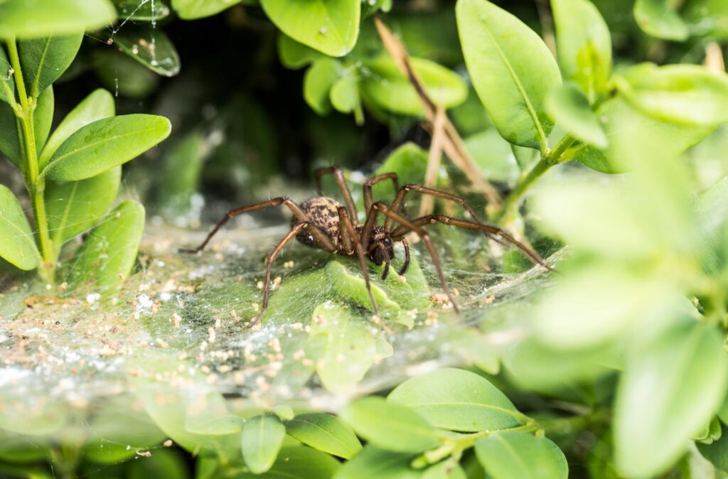
Funnel-Web Spiders (Family Agelenidae): These spiders build funnel-shaped webs in grass, under rocks, or in other sheltered locations. They wait at the entrance of their funnel for prey to stumble into their web. They are effective at catching ground-dwelling insects like ants, beetles, and crickets. Funnel-web spiders are often mistaken for hobo spiders, which are more venomous.
Creating a Spider-Friendly Garden: The Essentials
Now that you understand the benefits of spiders and can identify some common species, let’s explore practical strategies for attracting and retaining these beneficial creatures in your garden.
Provide Shelter and Hiding Places: Spiders need shelter to protect themselves from predators and the elements. Providing a variety of hiding places will encourage them to take up residence in your garden. Consider these options:
- Leaf Litter: Leave a layer of leaf litter in some areas of your garden. This provides a moist, sheltered environment for ground-dwelling spiders like wolf spiders.
- Rocks and Stones: Stack rocks and stones to create crevices and hiding places for spiders.
- Woodpiles: A small woodpile can provide excellent shelter for spiders, as well as other beneficial insects.
- Dense Vegetation: Plant dense shrubs and groundcovers to provide hiding places for spiders.
Plant a Diverse Range of Plants: A diverse range of plants will attract a wider variety of insects, providing a food source for spiders. Choose plants that bloom at different times of the year to ensure a continuous supply of food. Native plants are particularly beneficial, as they are adapted to the local climate and attract native insects.
Avoid Pesticides: As mentioned earlier, pesticides can indiscriminately kill beneficial insects, including spiders. Avoid using pesticides whenever possible. If you must use them, choose selective pesticides that target specific pests and minimize the impact on non-target organisms. Consider using organic pest control methods, such as hand-picking pests, using insecticidal soap, or introducing beneficial nematodes.
Provide a Water Source: Spiders need water to survive. Provide a shallow dish of water with pebbles or stones for them to climb on. This will prevent them from drowning. You can also create a small pond or fountain to provide a water source for spiders and other wildlife.
Mulch Your Garden: Mulch helps to retain moisture in the soil, creating a favorable environment for spiders and other beneficial organisms. Organic mulches, such as wood chips or straw, also provide shelter and food for spiders.
Reduce Night Lighting: Artificial light can attract insects, which can then attract spiders. However, excessive light can also disrupt the natural behavior of spiders and other nocturnal creatures. Reduce night lighting whenever possible to create a more spider-friendly environment.
Specific Strategies for Attracting Different Spider Species
While the general guidelines above will benefit all garden spiders, you can tailor your approach to attract specific species.
Attracting Orb-Weaving Spiders: To attract orb-weaving spiders, focus on providing support structures for their webs. Tall plants, shrubs, and fences can all serve as anchor points for their webs. You can also string up twine or wire to create additional web-building opportunities. Plant flowers that attract flying insects, such as daisies, sunflowers, and zinnias.
Attracting Jumping Spiders: Jumping spiders prefer sunny locations with plenty of vegetation to hunt in. Plant a variety of flowering plants and herbs to attract insects. You can also provide small rocks or stones for them to perch on. Avoid using pesticides, as jumping spiders are highly sensitive to chemicals.
Attracting Wolf Spiders: Wolf spiders prefer ground-level habitats with plenty of leaf litter and mulch. Avoid disturbing their habitat by raking leaves or tilling the soil. Provide rocks and stones for them to hide under. You can also create a small compost pile to attract insects, which will then attract wolf spiders.
Attracting Crab Spiders: To attract crab spiders, plant a variety of flowering plants with different colors and shapes. This will provide them with a diverse range of hunting opportunities. Avoid using pesticides, as crab spiders are highly sensitive to chemicals. You can also provide small dishes of water for them to drink.
Attracting Funnel-Web Spiders: Funnel-web spiders prefer sheltered locations with plenty of grass and debris. Avoid mowing the lawn too short and leave some areas of the garden undisturbed. Provide rocks and stones for them to build their funnels under. You can also create a small brush pile to provide additional shelter.
Troubleshooting Common Issues
Even with the best efforts, you may encounter some challenges when trying to attract spiders to your garden.
Lack of Spiders: If you’re not seeing many spiders in your garden, it could be due to a lack of food, shelter, or water. Review the strategies above and make sure you are providing the essential resources for spiders to thrive. It may also take time for spiders to colonize your garden, so be patient.
Spider Bites: While most garden spiders are harmless, it’s important to be aware of the potential for spider bites. Wear gloves when gardening and avoid disturbing spiders in their webs or hiding places. If you are bitten by a spider and experience severe symptoms, seek medical attention.
Spider Webs in Unwanted Locations: While spider webs are a sign of a healthy garden ecosystem, they can sometimes be unsightly or inconvenient. If you find spider webs in unwanted locations, simply remove them with a broom or hose. The spiders will likely rebuild their webs elsewhere.
Other Pests: Even with a healthy spider population, you may still encounter other pests in your garden. Spiders are not a silver bullet for pest control, and you may need to supplement their efforts with other organic pest control methods. Consider using row covers, companion planting, or introducing beneficial insects to control specific pests.
Beyond Pest Control: The Intrinsic Value of Spiders
While spiders are undoubtedly valuable for their pest control abilities, their importance extends beyond mere utility. They are fascinating creatures with intricate life cycles and unique behaviors. Observing spiders in your garden can be a rewarding experience, providing insights into the complex web of life that surrounds us.
By creating a spider-friendly garden, you are not only benefiting your plants but also contributing to the conservation of biodiversity. Spiders are an integral part of the ecosystem, and their presence is a sign of a healthy and thriving environment. So, embrace the spiders in your garden, appreciate their unique contributions, and enjoy the benefits of natural pest control.
Conclusion: Embrace the Eight-Legged Allies
Attracting beneficial spiders to your garden is a simple yet powerful way to promote natural pest control, enhance biodiversity, and create a healthier ecosystem. By providing shelter, food, and water, and by avoiding pesticides, you can transform your garden into a spider-friendly sanctuary. Embrace these eight-legged allies and reap the rewards of a vibrant, balanced, and pest-free garden.


